Friday, May 6, 2011

Concluding Thoughts

Overall, the product is successful at the functions it is intended to accomplish: detecting pulse, accounting for easy home use, and allowing for data collection. However, if more time and sophisticated technology were available, these resources would have been dedicated to developing a more advanced Asthma-Ox that was capable of detecting oxygen concentration and preventing IR light interference.

With the end of this project marks the end of the class! Paul and I had so much fun, and although the Arduino's temperament did make us want to cry at certain points, we had a lot of fun working with each other, our classmates, our awesome TAs Harsh and Yash, and of course, Dr. Bogen, our professor!

Device Benefits!

Feature

Benefits

Pulse Sensing Light

This alerts the patient to whether their pulse is actually being taken correctly. It also allows the patient to quickly count their own pulse by counting each blink.

Timer

The timer allows for easy monitoring of time. It allows the patient to steady their finger before they start recording their pulse and provides an amount of time that is ample enough for them to record a number that can easily be doubled to obtain a pulse. It thus saves the patient time by providing them with a convenient and accurate method of keeping track of time.

Value Output

The value output allows the patient to actually take the values generated by the IR sensor and develop a graph that charts their pulse over time in a simple program like Excel. By placing a correction in the raw values generated, the values will also generate a smoother curve making this process even easier for the patient. It also allows them to possibly update their doctors with this data in case of emergency.


The current device provides asthma patients with the benefit of being able to easily track and monitor their pulse at home, and thus overall the effects of an attack on their respiratory and circulatory systems. Unfortunately, due to an inability to test the success of the device measuring oxygen concentration, it cannot actually give the patient’s blood oxygen saturation levels. As such, this is a weakness of the product. If better technology and time had been available, it would have been invested into finding a way for the product to actually measure oxygen concentration. If the product had been able to actually monitor the concentrations, it would have proven to be a more effective product and more competitive against other pulse oximeters. Unfortunately, due to time constraints resulting from a delay caused by reverse engineering the counterfeit Nellcor sensor, it was not feasible to develop a prototype that would limit extraneous IR light interference. With more time, an actual prototype of the IR LED and sensor casing could have also been developed. This would have limited some of the error involved with the current set-up of the product.

Circuit Diagram

Fritzing is a pretty cool way to show the diagram of the circuit. There were a LOT of wires moving around in this project, but hopefully this clears up a little bit of the confusion.

Pictures and Videos of Our Project!

Now that Paul has taken you through the project through the code and the descriptions, we thought it would be cool for us to show you the project in action =) We took some pictures of the device as well, so enjoy!!


The circuit for the timer with the green LED and buzzer:


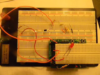
The main circuit itself!

Ugh, and as Paul and I discovered, counterfeit sensors aren't fun. Neither, apparently, is finding a replacement IR sensor to be used. It took the exploration of 7 sensors collected from 3 different labs in the Engineering school to find the right one! Check out the progression...

Thursday, May 5, 2011

The Final Project: Our Code

While finding the correct pieces and circuitry proved to be the hardest part of our project, luckily crafting a code proved to be easier. Below is the final code we settled on for our device. It proved to be the easiest way to manipulate the Arduino to allow us to achieve success.


Arduino Program:
int redled = 4;
int IRsensor = 0;
unsigned int A = 440;

double alpha = 0.75;
int period = 20;
double change = 0.0;
int greenPin = 8;
int buzzer = 7;
int clock = 998;
int sec = 0;

void setup()                 
{

pinMode(redled, OUTPUT);
pinMode(greenPin, OUTPUT);

}

void loop()                  
{
  
    static double oldValue = 0;
    static double oldChange = 0;
    int rawValue = analogRead(IRsensor);
    double value = alpha * oldValue + (1 - alpha) * rawValue;
    change = value - oldValue;
    
    digitalWrite(redled, (change < 0.0 && oldChange > 0.0));
  
    oldValue = value;
    oldChange = change;
    delay(period);
   
    Serial.print(rawValue);
    Serial.print(",");
    Serial.println(value);
    }
void loop()                 
{
   delay(clock);
 sec = sec + 1;

 if (sec <= 30)
  {
    digitalWrite(greenPin, HIGH);
  }
 
if (sec == 30)
  {
    tone(buzzer,A);
  }
 
if (sec > 30 && sec < 60)
  {
    noTone(buzzer);
    digitalWrite(greenPin, LOW);
     }

if (sec == 59)
  {
    sec = 0;

The Final Project: Specifications of our Device

Below is a list of specifications relating to our device. Each was chosen to provide the user with a better experience when using the product:


Specification:
Value, Value Range, or Quality:
Rationale:
Counting Time Cycle
1 Minute (30 seconds “On,” 30 Seconds “Off”)
After turning on the machine, the patient has 30 seconds to prepare themselves. The next 30 seconds is used for monitoring to allow for an accurate pulse while not requiring the patient to stay for a full minute.
Red LED
Pulse detection (Either On or Off)
The LED is there to help the patient ensure that a correct reading is occurring. If the light is blinking spastically, this signals to the patient that there is either some interference or the patient is not remaining still. If the light is not blinking at all then there is something wrong with the system as this symbolizes no interruption in the detection of IR light.
Serial Monitor Output
Raw values and “alpha value” corrected values
The numbers displayed on the Serial monitor are there to allow for the user to see the actual value changes from the IR sensor. This helps with troubleshooting and also allows for the alpha value correction to smooth out the number series in case graphing is needed.
Serial Baud Rate
57600 or 115200
In order to successfully detect changes in IR light transmittance, the baud rate for the serial monitor must be at one of the highest possible levels.
Resistor attached to the IR LED
2 kΩ
Using a potentiometer, this resistance value was calculated to be the best resistor value to allow for successful pulse detection.

The Final Project: How Our Device Works


Block Diagram of the Device:
           

As seen in the block diagram, the device is broken into two main parts. The first is what actually detects the pulse. This is accomplished through the transmission of infrared light from the IR LED to the IR receiver. As the infrared light passes through the person’s finger, changes in the transmission of light are caused by the person’s pulse. These changes in transmission are then detected by the IR sensor. The IR sensor is connected to the analog pin. The numbers relating to the transmission of the infrared light to the receiver are then taken in by the Arduino board and are the same numbers that are displayed on the Serial Monitor. The Serial Monitor in our program displays the raw value as well as a corrected value meant to smooth the function if the values were to be graphed. As seen in the block diagram, this occurs after the program (documented in the Appendix) detects changes in the numbers transmitted from the receiver by defining specific variables each time the loop is run; this is the second box on the left side of the block diagram. When a change is detected in these variables, the Red LED in serial pin 4 will blink. If there is no change detected in the variables, the program is coded using the “digitalWrite” function so that the Red LED will remain constantly lit.

The timer loop runs separately from the rest of the device.  By defining a clock, and setting up the Arduino so that it records time, it was capable to make a timer. As seen in the block diagram, the time at which most functions of the timing portion of the device are defined is 30 seconds. Once the timer hits 30 seconds, this triggers the buzzer to go off and the Green LED to light up. The device is also programmed to reset itself once 60 seconds have passed. The loop thus causes the device to go through the cycle all over again and the buzzer and light to activate again at time equals 30 seconds.

The Final Project: About Our Device

After out initial thoughts, the project did not turn out exactly as we had planned. Below though you will find some basic information about our device:

Need for this Device:
            Asthma is an allergic inflammatory disease of the airways that involves an immune response which results in the body’s use of white blood cells such as mast cells, eosinophils, macrophages, fibroblasts, and neutrophils. These inflammatory changes end up resulting in widespread airflow obstruction which can vary in location and degree between asthma attacks. This inflammation can improve either spontaneously or with the appropriate therapy, such as an inhaler for example. Over time, the inflammation that asthma sufferers experience can progress to increased airway irritability and other inflammatory responses and airflow obstruction due to the inhalation of allergens and even cold air. The onset of an asthma attack can have serious effects on the respiratory and circulatory system (Arm and Sheffer, 2008).

            In the United States, 17.5 million adults and 7.1 million children suffer from asthma (CDC, 2010). Obviously, this is a large population that must manage asthma attacks on a pretty regular basis. These patients, most of the time, do not have direct access to medical attention when they suffer from an asthma attack. This is because asthma can be triggered by many environmental factors and physical situations. The main objective of this device is to thus address this specific target population and help them better deal with their asthma and its symptoms.


The Competition:
            The goal of our project was to create a pulse oximeter targeted to asthma patients. Oximetry is the monitoring of the oxygen concentration of the blood. Thus pulse oximeters not only monitor the patient’s blood oxygen concentration but also the patient’s pulse. Currently, there are many pulse oximeters on the market. Their prices range very widely though with the cheapest at prices around $22.89 to the most expensive, found in our research, being approximately $1,125.00 (Amazon). Two companies that continually came up in the research and believed to be two of the larger producers of pulse oximeters were Nonin and Nellcor.

            While there are many pulse oximeters on the market, their prices vary greatly. One may wonder why this is exactly. A lot of this is most likely due to how successful and well respected each different manufacturer is and how high tech each machine is. One issue that was witnessed first hand was that there are a lot of counterfeit pulse oximeters and pulse oximeters parts on the market. Initially the plan was to reverse engineer our machine from a cheap pulse oximeter meant to be plugged into a computer. This piece had been bought from a website that claimed it was a Nellcor (a major manufacturer of pulse oximetry products) product online. This proved to be unsuccessful because the piece ordered was not real. This was proven when the product code did not line up with any actual Nellcor products. This leads to the first advantage of the Asthma-Ox product: it works and it is affordable. Another advantage is that the product allows for data output which can actually then display the heart beat itself. Most other pulse oximeters merely attach to the finger and just give a reading. While our machine does allow for a computer monitoring, this also gives it the disadvantage of it not being as portable as other pulse oximeters on the market. Another disadvantage of our machine is that it cannot actually measure the oxygen saturation on the blood.


Here are some pictures of the competition: